SECYC 2023 Flux Decoder Badge

The Flux Decoder

The Future Is In Your Hands!

Doc Brown needs your help!!! He has been hard at work building the Flux Decoder. However, he needs your help! Doc Brown wasn’t able to finish the prototype and left it up to you to finish building. Complete the solder job to power up the Flux Decoder to 1.21 gigawatts. Then, use the integrated decoder to solve other challenges!

Looking for soldering instructions?

Check out Kyle’s YouTube video!

Looking for badge source code?

Check out the GitHub Repository!

Programming the board

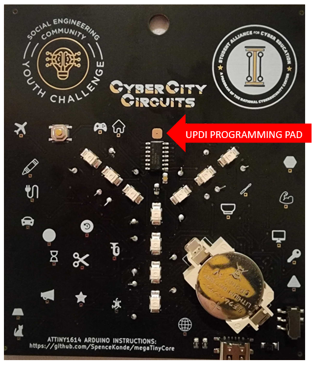
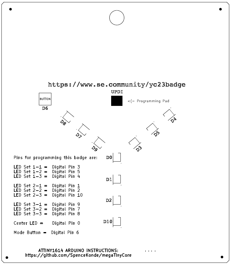
The board comes preprogrammed. However, if you want to program it with your own code. Here is some helpful notes. Also, we have two programmers in the village we can loan you! 

Programming With Arduino - Steps

  1. Add board manager (file > prefs) http://drazzy.com/package_drazzy.com_index.json
  2. Download MegaTinyCore through the board manager. Use the following settings:
    1. (tools > board): Third option lists ATTINY1614.
      1. DO NOT use the option with Optiboot
    2. (tools > chip): ATTINY1614
    3. (tools > clock): 8MHz Internal
    4. (tools > port): Comm port of your UPDI programmer
    5. (tools > programmer): jtag2updi
  3. Connect a USB-C cable to your computer to the port on the badge.
    1. This will provide POWER and GROUND to the badge. this way, you’ll only need to use the red line from the programmer.
  4. Upload using (sketch > upload using programmer).
  5. Use a UPDI programmer. You can build one using an Arduino Nano. Or borrow one from us at the SEC Village!
    1. This is called ‘jtag2updi’ and more information can be found at the following link: https://github.com/ElTangas/jtag2updi
  6. Connect the red wire of the programmer to the UPDI pad above the microcontroller.
  7. Upload the program from Arduino!

Pins available to control are:

  • LED Set 1-1 = Digital Pin 3
  • LED Set 1-2 =  Digital Pin 5
  • LED Set 1-3 =  Digital Pin 4
  • LED Set 2-1 =  Digital Pin 1
  • LED Set 2-2 =  Digital Pin 2
  • LED Set 2-3 = Digital Pin 10
  • LED Set 3-1 =  Digital Pin 9
  • LED Set 3-2 =  Digital Pin 7
  • LED Set 3-3 =  Digital Pin 8
  • Center LED = Digital Pin 0
  • Mode Button = Digital Pin 6

Flux Decoder Pins

Pins available to control are:

You can interface with the following pins on the badge if you want to customize how it works!

  • LED Set 1-1 = Digital Pin 3
  • LED Set 1-2 =  Digital Pin 5
  • LED Set 1-3 =  Digital Pin 4
  • LED Set 2-1 =  Digital Pin 1
  • LED Set 2-2 =  Digital Pin 2
  • LED Set 2-3 = Digital Pin 10
  • LED Set 3-1 =  Digital Pin 9
  • LED Set 3-2 =  Digital Pin 7
  • LED Set 3-3 =  Digital Pin 8
  • Center LED = Digital Pin 0
  • Mode Button = Digital Pin 6